 RFID technology is based on clear scientific principals. Tags gather the projected energy of radio waves in an electromagnetic field. The tags then reflect back an altered signal using a technique called
back-scatter which the antennas receive. Because it is a science, it is often assumed that an expert can accurately predict both the read performance of a tag on any item and the distance it can be read from, just by looking at the system. Unfortunately, reality is much more complex, making RFID operation seem like black magic. In most environments, RFID produces strange outcomes. – often counter intuitive. Usually, the outcome ends up making sense once investigated, but it rarely is what you would first expect.
Thank you to RR Donnelley & Sons Co. for sending us samples of their Custom Wave RFID labels. Now everybody knows about RR Donnelley’s custom antenna printing right? (You don’t? Well you should. Check out this article about them in RFID Journal!)
We received four different passive UHF tags which we tested in two different environments.
- Inside a warehouse
- Outside in an open parking lot
Below are the test results.
| CW-100-04U7 | CW-100-08MR6 | |
| Inlay | 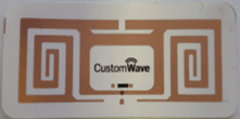 |
 |
| Inlay Measurements | 18 mm * 44 mm | 22 mm * 60 mm |
| Warehouse Read Range | 2.2 meters | 6.22 meters |
| Outdoor Read Range | 2.13 meters | 3.35 meters |
| CW-100-01MR6 | CW-100-05U7 | |
| Inlay |  |
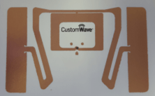 |
| Inlay Measurements | 95 mm * 8 mm | 50 mm * 30 mm |
| Warehouse Read Range | 6.83 meters | 9.19 meters |
| Outdoor Read Range | 4.72 meters | 5.18 meters |
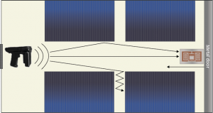
Why is there such a significant difference in read range between the two environments if we are using the same reader and the same tags? Most likely the answer is due to reflection of RF energy. The diagram below shows the environment in our warehouse which we tested. The tags were being read down a corridor bordered by pallets of paper products. The image shows how the RF field might be reflected to improve our range.
Warehouse Test Diagram
The warehouse test diagram illustrates a reader with energy reflected down the corridor. Only a small amount of the energy output from the reader is able to escape through space between the pallets and up into space above the pallets. In this warehouse trial, the tag was able to be read from further away because there was more RF energy available to power the tag than there would have been in the open. Additionally, the large metal door behind the tag could have reflected energy back towards the tag, which would give the tag a double dose of RF energy.
Outside, most of the RF energy that was not oriented directly at the tag was lost because it escaped into space. The RF energy around the tag was weaker and it could not power the tag at the longer distances.
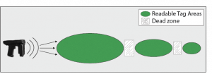
Reflection not only changes your ability to read a tag, but also creates strange tag reading situations. During the outside tests, we found what we thought was the max read range for the CW-100-05U7 at 4 meters. At 4.5 meters, we could not read the tag. However, at 5 meters, the reader found the tag again. Why could the reader pick up a read from 5 meters but not 4.5 meters? Of course the answer is reflection. The image below demonstrates the phenomenon that we saw.
RF Energy Fields
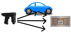
Passive UHF tags are dormant until they are powered by enough energy to send a response. In the example above, the RF energy is powerful enough to read a tag anywhere in the first area without any reflection. Then there is a small gap between fields. There is likely energy in the gap between the blue areas, but it is not enough to power the tag. In the small blue areas to the right of the large oval, the RF energy is enhanced via reflected RF waves increasing the energy available to the tags. In this situation, it may have reflected from the ground or nearby vehicles, as shown in the image below.
RF Reflection
What can we take from this?
Testing is critical as it is almost impossible to consider all factors which you may see in your actual environment. More than focusing solely on the tag and reader, consider the places where the field will be at its weakest and adjust the tag or antenna locations if possible.
You can see a video of how this works in practice below. The LED board which shows the , showing field strength with the Telaeris UHF Sensor.
RF reflection is one of many aspects of an RFID system to consider. For more information on RFID systems please contact [email protected]. For more information about the Custom Wave RFID labels, check out their website at https://www.rrdonnelley.com/.
Note: Handheld RFID readers are not usually the best solution for long distance scanning. Fixed readers and antennas will typically provide a longer read range as the readers project more RF energy.


0 Comments