

A few months ago, we published a history of where Weigand came from and a “light-on-technical-details” overview of how it works. For those of us that are more engineer-y, it left a bit to be desired. For me in particular, I recently was doing some low level work with one of my engineers. We were monitoring the lines from a badge reader and I couldn’t recall what the spec for the pulse width should be. For most people, this level of detail is overkill, but since for those of you who get down and dirty with D0/D1 of Wiegand, this post is for you.
As you might recall from our earlier post, Wiegand is used interchangeably to describe a number of things – an electronic effect, an access card, a bit stream associated with a card, or a specific reader-to-card interface. We are going to be referring to Wiegand as the signal that comes from an access control reader, out of the Data 0 (D0) and Data 1 (D1) lines. This data is interpreted as an access card number by parsing the bit stream.[/vc_column_text][vc_column_text]The Wiegand standard is only a de facto standard, but there is a Security Industry Association (SIA) document “Access Control Standard Protocol for the 26-bit Wiegand(tm) Reader Interface” which describes an agreed standard that should work with all manufacturers’ panels. Some of the basic information found in this document is found below.
When a reader with a Wiegand interface is hooked up to an access panel, it generally includes 6 lines with the below color scheme, which interfaces with the back end access panel.
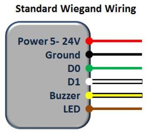
D0 (green) and D1 (white) outputs are almost universally colored Wiegand readers
Back when Telaeris was developing our XPressProx mobile proximity reader to read HID Prox cards, we needed to demodulate the data directly from the RF signal (*). Once we decoded this signal, the data was pushed both over a USB connection as well driving the signal as over standard D0/D1 Wiegand lines. When we hooked up our Agilent 54622D Oscilloscope to the data lines and presented different cards to the reader, these are examples of what we saw:
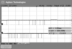
26 bit output
26 output bits 10000000100000010111001011
parity even 1 parity odd 1
00000001 Facility=1
BadgeID=741 0000001011100101
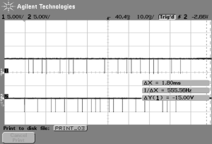
36 bit output
36 output bits 011011001011001000100101101011100101
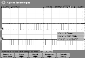
37 bit output
37 output bits 0001001000000011111101000001011001000
The 26 bit card is parsed out for you to see as the bit format is almost universally standard. The 36 and 37 bit cards are part of HID’s corporate 1000 line, which often mix up the location of the bits in weird and wonderful ways. The security in these cards is often simply that it is difficult to know how a bit stream might be parsed. These bitstreams can come in a variety of lengths, all the way up to 200 for some US Government PIV cards.

0 Comments